- Current location:
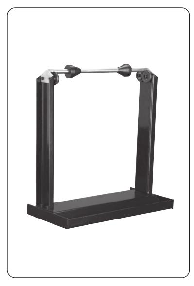
Motorcycle Wheel Balancing Stand
Motorcycle Wheel Balancing Stand
WARNINGR
Read this material before using this product.
Failure to do so can result in serious injury.
SAVE THIS MANUAL.
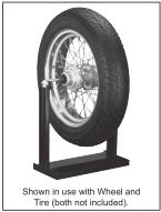 Shown in use with Wheel and Tire(both not included)
When unpacking, make sure that the product is intact and undamaged.
If any parts are missing or broken, please contact us as soon as possible.
Specifications
Dual purpose stand to balance mounted tires.
Accepts up to 13-7/8” W tires, 12-1/2” wide
hubs and 1.59”/15 mm to 1.46”/37 mm axles.
Use Precautions
1.This product is not a toy. Do not allow
children to play with or near this item.
2.Use for intended purpose only.
3.Inspect before use; do not use if
parts are loose or damaged.
4.Maintain product labels and nameplates.
These carry important safety information.
If unreadable or missing, contact
Harbor Freight Tools for a replacement.
Important Safety Information
Assembly Precautions
1.Assemble only according
to these instructions.
Improper assembly can create hazards.
2.Wear ANSI-approved safety goggles and
heavy-duty work gloves during assembly.
3.Keep assembly area clean and well lit.
4.Keep bystanders out of the
area during assembly.
5.Do not assemble when tired or when under
the influence of drugs or medication.
Assembly Instructions
Read the entire important safety information
section at the beginning of this document including
all text under subheadings therein
before set up or use of this product.
Assembly
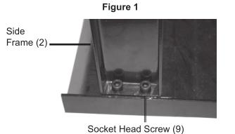
1.Attach each Side Frame (2) to the Base (1):
With the face of the Side Frame (2) facing
inward, insert two Socket Head Screw
(9) down through the Side Frame and
through the Base (1). Secure in place
with two Lock Nuts (10)-see Figure 1.
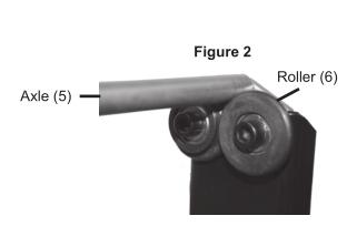
Figure 2
2.Set the Axle (5) onto the Rollers (6)
as shown in Figure 2.
Operating Instructions
1.Prior to use check to make
certain that the Axle is straight,
without any bends or damage.
2.Back off both Socket Set Screw (12) and
slide off one of the Centering Cones (4) from
Axle (5). Support the wheel of the motorcycle
in an upright position and slide the Axle (5)
through the wheel hub and replace the
Cone. Center the wheel on the Axle and
slide both Cones securely against the hub.
Tighten the Socket Cap Screws (12).
3.Lift the wheel and position the Axle over
the Rollers (6). Gently spin the wheel. The
heavier side would roll to the bottom. With
a chalk mark the tire at the upper most
location (across from the heavy side).
4.Lift the wheel assembly from the
balancing weight (not supplied) to the
inner edge of the rim and reposition the
wheel assembly over the Rollers (6).
NOTE: Use lightest possible weights.
With try and error, you should be able to
establish approximate required weights.
5.Gently spin the tire. Repeat steps 3 and 4
placing balancing weights on
alternative sides of the tire rim.
6.Continue to counter balance the wheel until
it spins evenly and does not repeatedly
7.Once the wheel is balanced, remove the
one Socket Set Screw (12) and remove
the Centering Cone (4). Remove the Axle,
replace the Cone and tighten the screw.
Place the axle on the rollers.
Maintenance
1.Before each use, inspect the general
condition of the Balancing Stand.
Check for loose screws, misalignment
or binding of moving parts, cracked or
broken parts, and any other condition
that may affect its safe operation.
2.Periodically lubricate contact points
and Rollers with grease.
Replacing Rollers
1.Rollers (6) and Bearings (7) can be replaced
by removing Socket Head Screw (11) and
pulling Rollers off of the Balancing Stand.
2.Replace with new Rollers (6) and
Bearings (7) and secure with Socket
Set Screw (11). See Figure 2.
3.When not in use, store in a safe
location away from children.
Please Read the Following Carefully.
The manufacturer and/or distributor has provided the parts list and assembly diagram in this document as a reference tool only. Neither the manufacturer or distributor makes any representation or warranty of any kind to the buyer that he or she is qualified to make any repairs to the product, or that he or she is qualified to replace any parts of the product .In fact ,the manufacturer and/or distributor expressly states that all repairs and parts replacements should be undertaken by certified and licensed technicians, and not by the buyer. The buyer assumes all risk and liability arising out of his or her repairs to the original product or replacement parts thereto, or arising out of his or her installation of replacement parts thereto.
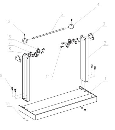
Parts List and Assembly Diagram
Parts List and Assembly Diagram | ||
Part | Description | Qty. |
1 | Base | 1 |
2 | Side Frame | 2 |
3 | Mounting Plate | 2 |
4 | Centering cone | 2 |
5 | Axle | 1 |
6 | Roller | 4 |
7 | Bearing | 4 |
8 | Sleeve | 4 |
9 | Socket Head Screw M8*20 | 4 |
10 | Lock Nut M8 | 4 |
11 | Socket Set Screw M8*25 | 4 |
12 | Socket Head Screw M6*15 | 2 |
Note: Some parts are listed and
shown for illustration purposes only,
and are not available individually
as replacement parts.